pysdic.create_triangle_3_heightmap#
- create_triangle_3_heightmap(height_function=<function <lambda>>, frame=None, x_bounds=(-1.0, 1.0), y_bounds=(-1.0, 1.0), n_x=10, n_y=10, first_diagonal=True, direct=True, uv_layout=0)[source]#
Create a 3D
MeshXY-plane mesh with variable height defined by a surface function.The surface is defined by a function that takes two arguments (x and y) and returns a scalar height z. The returned value is interpreted as the vertical position of the surface at that point.
The
frameparameter defines the orientation and the position of the mesh in 3D space. The (x, y) grid is centered on the frame origin, lying in the local XY plane. The height (z) is applied along the local Z-axis of the frame.The
x_boundsandy_boundsparameters define the rectangular domain over which the mesh is generated.n_xandn_ydetermine the number of vertices along the x and y directions, respectively. Nodes are uniformly distributed across both directions.Note
n_xandn_yrefer to the number of vertices, not segments.The height function must return a finite scalar value for every (x, y) in the specified domain.
For example, the following code generates a sinusoidal surface mesh centered on the world origin:
from pysdic import create_triangle_3_heightmap
import numpy as np

surface_mesh = create_triangle_3_heightmap(
    height_function=lambda x, y: 0.5 * np.sin(np.pi * x) * np.cos(np.pi * y),
    x_bounds=(-1.0, 1.0),
    y_bounds=(-1.0, 1.0),
    n_x=50,
    n_y=50,
)

surface_mesh.visualize()
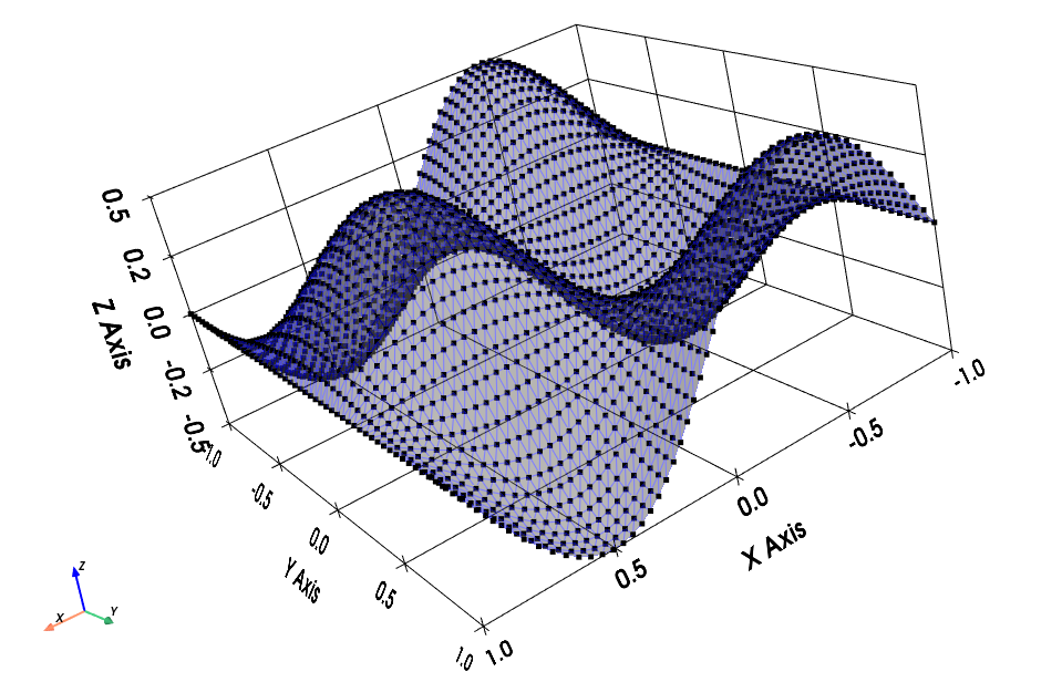
Sinusoidal height map over a square domain centered at the origin.#
Nodes are ordered first along the x direction, then along the y direction. So the vertex at y index
i_Yand x indexi_X(both starting from 0) is located at:mesh.vertices[i_Y * n_x + i_X, :]
Each quadrilateral face is defined by the vertices:
\((i_X, i_Y)\)
\((i_X + 1, i_Y)\)
\((i_X + 1, i_Y + 1)\)
\((i_X, i_Y + 1)\)
This quadrilateral is split into two triangles.
See also
Meshfor more information on how to visualize and manipulate the mesh.Artezaru/py3dframe for details on the
Frameclass.
- Parameters:
height_function (Callable[[float, float], float]) – A function that takes x and y coordinates and returns the corresponding height (z).
frame (
Frame, optional) – The reference frame for the mesh. Defaults to the canonical frame.x_bounds (Tuple[
float,float], optional) – The lower and upper bounds for the x coordinate. Default is(-1.0, 1.0).y_bounds (Tuple[
float,float], optional) – The lower and upper bounds for the y coordinate. Default is(-1.0, 1.0).n_x (
int, optional) – Number of vertices along the x direction. Must be more than 1. Default is10.n_y (
int, optional) – Number of vertices along the y direction. Must be more than 1. Default is10.first_diagonal (
bool, optional) – IfTrue, the quad is split along the first diagonal (bottom-left to top-right). Default isTrue.direct (
bool, optional) – IfTrue, triangle vertices are ordered counterclockwise for an observer looking from above. Default isTrue.uv_layout (
int, optional) – The UV mapping strategy. Default is0.
- Returns:
The generated surface mesh as a
Meshobject.- Return type:
Geometry of the mesh#
Diagonal selection#
According to the
first_diagonalparameter, each quadrilateral face is split into two triangles as follows:If
first_diagonalisTrue:Triangle 1: \((i_X, i_Y)\), \((i_X + 1, i_Y)\), \((i_X + 1, i_Y + 1)\)
Triangle 2: \((i_X, i_Y)\), \((i_X + 1, i_Y + 1)\), \((i_X, i_Y + 1)\)
If
first_diagonalisFalse:Triangle 1: \((i_X, i_Y)\), \((i_X + 1, i_Y)\), \((i_X, i_Y + 1)\)
Triangle 2: \((i_X, i_Y + 1)\), \((i_X + 1, i_Y)\), \((i_X + 1, i_Y + 1)\)
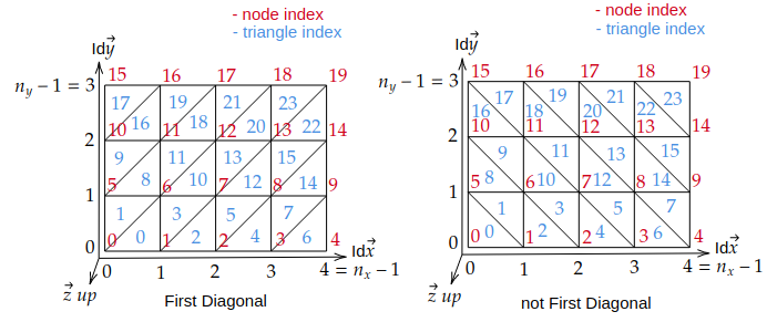
Diagonal selection for splitting quadrilaterals into triangles.#
Triangle orientation#
UV Mapping#
The UV coordinates are generated based on the vertex positions in the mesh and uniformly distributed in the range [0, 1] for the
OpenGL texture mapping convention(See https://learnopengl.com/Getting-started/Textures). Several UV mapping strategies are available and synthesized in theuv_layoutparameter.An image is defined by its four corners:
Lower-left corner : pixel with array coordinates
image[height-1, 0]but OpenGL convention is (0,0) at lower-leftUpper-left corner : pixel with array coordinates
image[0, 0]but OpenGL convention is (0,1) at upper-leftLower-right corner : pixel with array coordinates
image[height-1, width-1]but OpenGL convention is (1,0) at lower-rightUpper-right corner : pixel with array coordinates
image[0, width-1]but OpenGL convention is (1,1) at upper-right
The following options are available for
uv_layoutand their corresponding vertex mapping:uv_layout
Vertex lower-left corner
Vertex upper-left corner
Vertex lower-right corner
Vertex upper-right corner
0
(0, 0)
(0, n_y-1)
(n_x-1, 0)
(n_x-1, n_y-1)
1
(0, 0)
(n_x-1, 0)
(0, n_y-1)
(n_x-1, n_y-1)
2
(n_x-1, 0)
(0, 0)
(n_x-1, n_y-1)
(0, n_y-1)
3
(0, n_y-1)
(0, 0)
(n_x-1, n_y-1)
(n_x-1, 0)
4
(0, n_y-1)
(n_x-1, n_y-1)
(0, 0)
(n_x-1, 0)
5
(n_x-1, 0)
(n_x-1, n_y-1)
(0, 0)
(0, n_y-1)
6
(n_x-1, n_y-1)
(0, n_y-1)
(n_x-1, 0)
(0, 0)
7
(n_x-1, n_y-1)
(n_x-1, 0)
(0, n_y-1)
(0, 0)
The table above gives for the 4 corners of a image the corresponding vertex in the mesh.
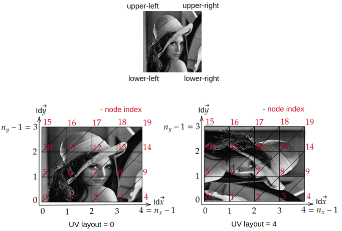
UV mapping strategies for different
uv_layoutoptions.#To check the UV mapping, you can use the following code:
import numpy as np
from pysdic import create_triangle_3_heightmap
import cv2

surface_mesh = create_triangle_3_heightmap(
    height_function=lambda x, y: 0.5 * np.sin(np.pi * x) * np.cos(np.pi * y),
    x_bounds=(-1.0, 1.0),
    y_bounds=(-1.0, 1.0),
    n_x=50,
    n_y=50,
    uv_layout=3,
)

image = cv2.imread("lena_image.png")
surface_mesh.visualize_texture(image)
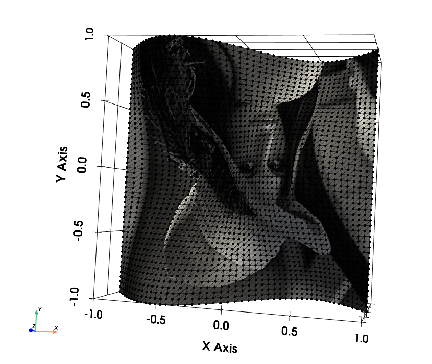
UV mapping of the Lena image on a sinusoidal height map.#